
Oli used this circuit
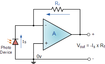
in an answer, and it pops up a lot on Google images too. But does it work? If it does a theoretical explanation will be welcome.
 ACCEPTED]
According to this, the photodiode does indeed produce a current even when there is zero volts across it; it's the short circuit current. Note that the reference direction of \$I_S\$ in the question's diagram is opposite that of the \$I_{SC}\$ of the diode so the output voltage is:
\$V_{OUT} = - I_S \cdot R_F = I_{SC} \cdot R_F\$
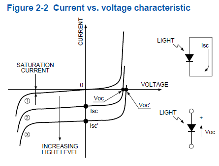
I found the above here [1].
A reasonable question to ask is how can a current be produced with zero voltage?
Remember that there's an internal E field through the depletion region even when the diode terminals are shorted together. Briefly, light generated EHPs in the vicinity of the depletion region are separated by the E field resulting in charge accumulating in the P and N sides (that's how \$V_{OC}\$ is developed). A short circuit allows a current to restore charge balance.
[1] http://sales.hamamatsu.com/assets/applications/SSD/photodiode_technical_information.pdfedited after Alfred's answer
The classic inverting amplifier is like this:
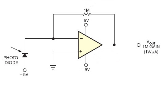
The photodiode will create a current, which will cause a voltage drop across the resistor. An opamp with negative feedback will try to make both inputs equal, so the inverting input will be at 0 V, and the current through the resistor will create a positive output voltage.
Why did I think the other circuit wouldn't work? If the diode creates a current you would suppose there's a voltage drop as well. Then the voltage at the inverting input would be higher than zero, and the opamp, trying to correct that, would see its output go all the way down to the negative rail.
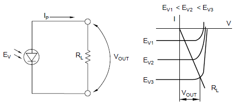
Alfred's graph shows however that the input can be driven down to 0 V by the output. It requires that the voltage across the diode can go down to zero, while there's still current. Here's another graph, from this document [1], which confirms Alfred's answer:
The circuit in your answer relies on the photoelectric effect [1] to amplify the photocurrent produced by the diode with a transimpedance amplifier.
The circuit in your question is relying on the photovoltaic effect [2] but the current direction is wrong (consider a solarcell with a single diode), and it only makes sense with finite gain (ie with an resistor in series with the cathode). There is also an implied photocurrent source in parallel with the diode.
Just how efficient a photodiode would be as a photovoltaic source I don't know but I suspect not very.
EDIT
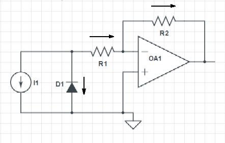
On second thoughts, R1 is not necessary since even if the diode is shorted, the photocurrent will still flow (again, consider shorting a solar cell).
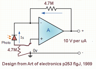
[1] http://en.wikipedia.org/wiki/Photoelectric_effectI got the circuit idea below from p253 circuit J, "Art of Electronics", 1989 version. Sharp application note also uses a resistor on the +Vin for an op amp and phototransistor, but does not explain what it does.
I tested the circuit below with and without the bottom resistor: I could see no effect when I pulled out the short over the bottom resistor: not even a change in gain. I am testing at very low light level pulses, using regular 850 nm and 830 nm diodes as "photodiodes". I got much better detection when the "photodiode" was reversed from the diagrams on this page. This is probably important only in low light levels (less than 1 mW/cm^2). When the diode was oriented as shown on this page, the output was not inverted, in contradtiction to everyone's comments. Maybe photodiode manufacturers declare the orientation reversed from what it actually is. A 0.0001 to 0.0047 uF capacitor over the feedback resistor helped reduce spikes on pulses, but made the spikes worse for very low light levels.
Using a back-biased 880 nm phototransistor with the op amp (fig 13 on the sharp application note) with a 830 nm diode supplying the light worked about 10 times better at low light levels than plain 830 nm LED as a detector if pulses were more than about 1 ms, and if a capacitor over the feeback resistor was used. It seems like 0.01 mW/cm^2 detection is possible.
The op amp is JFET for very low input currents.
Not sure if this helps but I just tested the circuit below on a breadboard and it works fine. The sensitivity is not great, needs a fair bit of light to register anything and the response is not linear but it definitely measures how much light the white led is shining on it. The resistance affects the sensitivity, more resistance = more sensitive - I tweaked it until it was how I wanted it, somewhere around 100k-300k I think.
The voltage at the output maxes out around 4v but I think that's an LM358 limitation.
The role of the "mysterious" 4.7 M bottom resistor in the clever H&H circuit solution (Page 253, Fig. J) can be easily revealed if we realize the fact that the circuit is single-supplied. Indeed, this is not shown in the diagram... but I think it is intentionally not drawn to make the reader think (what the main idea of the bestseller is).
Shortly, the resistor "lifts" the voltage drop across the "floating" photodiode above the ground thus ensuring a kind of a "self-biasing". I have illustrated the circuit operation in the picture below by means of voltage bars (in red) and current loops (in green). I will analyze it with pleasure.
First, imagine there is no light... so there is no current flowing... zero voltage drops across the resistors... zero input voltages... zero output voltage... the circuit is "dead"...
Then turn on the light. The "photodiode current source" produces the current IPH that flows through the path R2 -> V+ - > op-amp output -> R1 and creates the voltage drops VR1 and VR2. The op-amp senses a positive voltage difference at its inputs and begins increasing its output voltage VOA to zero it. When it reaches the equilibrium, its output voltage VOA = VR1 + VR2 fully compensates the sum of voltage drops across resistors (VR1 + VR2)... and the voltage across the photodiode is (almost) zero.
Figuratively speaking, the op-amp output acts as a negative "resistor" with resistance -(R1 + R2) that compensates the positive resistance R1 + R2... and the whole circuit (without the photodiode) behaves just as a piece of wire that shorts the photodiode.
Indeed, this trick does not work very well in the beginning when both op-amp input voltages are close to ground...